Normal pressure fire fighting pumps generate the water flow and pressure required to effectively extinguish fires. They are typically powered by electricity, diesel engines, or gasoline engines, ensuring reliable operation in emergency situations. Available in a variety of sizes and capacities to meet the specific needs of different firefighting scenarios, these pumps are designed with durability and performance in mind to ensure reliable, efficient operation in extreme conditions.


Product Details

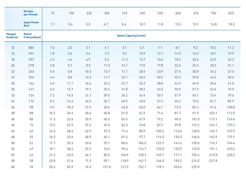
Products Detail
· Detailed Parameters:
Plunger Diameter: 60mm
Pump Speed: 477rpm
Theoretical Flow Rate: 161.84L/min
Effective Power: 11.37KW
· Drive Power and Method:
Fixed base with belt-driven transmission.
Powered by Y-series 11KW, 4-pole, three-phase asynchronous motor.
· Media Contact Materials:
Hydraulic End Cylinder: 304 stainless steel for corrosion resistance.
Valve Assembly: 17-4PH stainless steel for high strength.
Plunger: 304 stainless steel with Ni60 coating for wear resistance.
Product Parameters
|
3DP40 |
|
|
|
Pump type: 3DP40 |
|
Pressure (bar): 35 Mpa |
|
|
Flow rate (L/min): 160 L/min |
|
|
Motor power (KW): 11 KW 4-pole |
|
|
Medium: Water |
|
|
Medium temperature ℃: Normal |
|
|
Valve accessories configuration: 1.Pressure Regulating Valve 2.Vibration-resistant Pressure Gauge |
|
Working Principle
1. Impeller rotation generates centrifugal force
The impeller rotates at high speed, so that the liquid in the pump chamber obtains centrifugal force. The centrifugal force causes the liquid to be thrown to the outer periphery of the impeller and flow to the outlet of the pump.
As the impeller continues to rotate, the liquid is continuously accelerated and pressurized.
2. Forming a pressure difference to drive the liquid flow
At the center of the impeller, a certain vacuum area is formed due to the liquid being thrown out. This vacuum area allows the external liquid to be continuously sucked into the pump chamber through the water inlet pipe under the action of atmospheric pressure to replenish the liquid thrown out.
Under the action of the impeller, a pressure difference is formed between the water inlet pipe and the water outlet pipe, and the liquid can flow from the low-pressure area (water inlet pipe) to the high-pressure area (water outlet pipe).
3. Output high-pressure water flow
After being accelerated and pressurized by the impeller, the liquid flows out of the outlet of the fire pump at a higher pressure and flow rate and enters the fire pipe network.
The fire pipe network transports the high-pressure water flow to various fire-fighting equipment, such as fire hydrants, sprinkler heads, etc., for fire extinguishing or fire control.
Advantages
1. Designed to deliver high water flows at constant pressure.
2. Easy to operate.
3. Can handle large volumes of water without overheating or other mechanical issues.
4. Designed to pump water from a variety of sources such as hydrants, tanks, pools, reservoirs, and lakes, making it a versatile and adaptable firefighting device.
Debugging method
1. Inspection before debugging
Before debugging, the installation of the fire pump should be fully checked, including whether the pipeline connection is firm, whether the valve is in the correct position, whether the electrical connection is correct, etc.
Check whether the appearance of the fire pump is damaged, whether the impeller rotates flexibly, and whether all parts are complete.
2. Water filling and exhaust
Open the valve on the water inlet pipeline and fill water into the fire pump until the entire pump cavity and water inlet pipeline are filled. During the water filling process, attention should be paid to remove the air in the pipeline. The exhaust can be exhausted by opening the exhaust valve on the pump body or setting an exhaust port at a high place.
3. Motor test run
When the fire pump is not connected to the pipeline, the motor is tested separately. Check whether the motor's direction is correct, whether the operation is smooth, and whether there is abnormal noise and vibration. The motor test run time is generally about 2 hours.
4. Fire pump test run
Connect the fire pump to the pipeline and start the fire pump for test run. During the test run, observe the operation of the fire pump, including whether the flow, pressure, vibration, noise, etc. meet the design requirements.
Check whether the switches of each valve are flexible and whether the check valve is working properly. At the same time, monitor the current, power and other parameters of the motor to ensure that the motor operates within the normal working range.
5. Debugging records
During the debugging process, the various parameters and operating conditions of the fire pump should be recorded in detail, including flow, pressure, motor current, power, vibration, noise, etc. The debugging record should be used as an important basis for the acceptance and maintenance of the fire pump.
6. Problem handling
If problems are found during the debugging process, they should be handled in time. If the flow or pressure is insufficient, it may be due to pipeline blockage, impeller damage or insufficient motor speed. They should be checked one by one and corresponding repairs or adjustments should be made. If the motor runs abnormally, it may be an electrical connection problem or a fault in the motor itself, which should be checked and repaired in time.
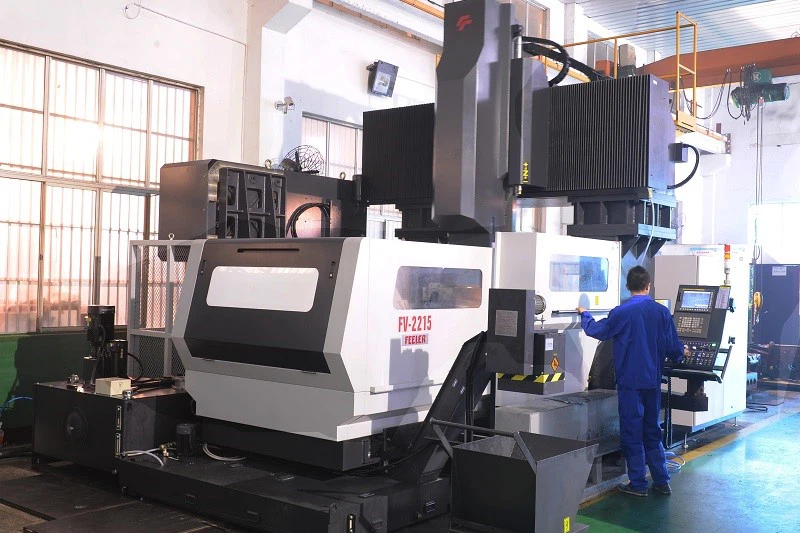
Processing Equipment
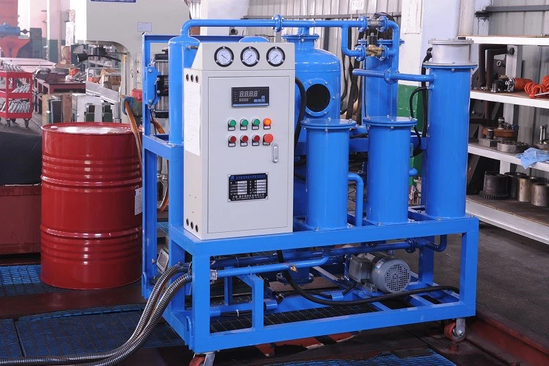
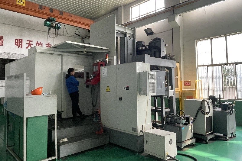

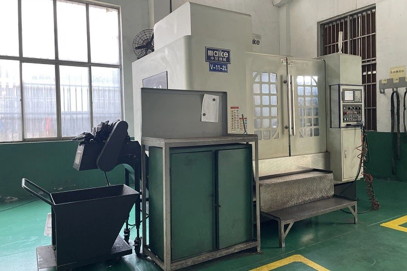

Hot Tags: normal pressure fire fighting pumps, China normal pressure fire fighting pumps manufacturers, suppliers, factory


